- Артикул:00-01049902
- Автор: Frank Ebel, Siegfried Idler, Georg Prede, Dieter Scholz
- Обложка: Мягкая обложка
- Издательство: FESTO (все книги издательства)
- Город: Germany
- Страниц: 212
- Год: 2010
- Вес: 530 г
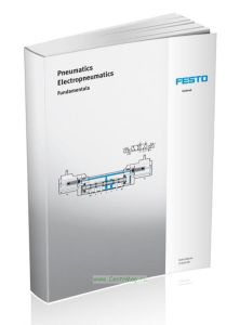
Pneumatics. Electropneumatics/Пневматика. Электропневматика
Книга на английском языке.
The use of air as a working medium can be traced back over thousands of years. Everyone is familiar with wind as a driving force for sailing ships and windmills.
The word pneumatics comes from the Greek word pneuma, meaning breath or breeze. Pneumatics is generally understood as the study of air movements and air processes.
Pneumatics and electropneumatics are successfully used in many areas of industrial automation.
Throughout the world, electropneumatic control systems are used to operate production, assembly and packaging systems. In addition, technological advances in materials, design and production methods have improved the quality and variety of the pneumatic components and in this way helped to extend their use.
Changing requirements and technical developments have dramatically altered the appearance of control systems. In the signal control section, the relay has increasingly been replaced by the programmable logic controller in many fields of application in order to meet the increased requirement for flexibility. And in the power section of electropneumatic control systems new concepts have been included that are tailored to the demands of industrial practice. Examples of these new concepts include valve terminals, bus networking and proportional pneumatics.
Contents
Foreword
1 Applications in automation technology
1.1 Overview
1.2 Characteristics of pneumatics
1.2.1 Criteria for working media
1.2.2 Criteria for control media
1.3 Development of pneumatic control systems
2 Basic concepts of pneumatics
2.1 Physical principles
2.1.1 Newton's law
2.1.2 Pressure
2.2 Properties of air
2.2.1 Boyle's law
2.2.2 Gay-Lussac's law
2.2.3 General gas equation
3 Compressed air generation and compressed air supply
3.1 Preparing the compressed air
3.1.1 Consequences of poorly prepared compressed air
3.1.2 Pressure level
3.2 Compressors
3.2.1 Reciprocating piston compressor
3.2.2 Diaphragm compressor
3.2.3 Rotary piston compressor
3.2.4 Screw compressor
3.2.5 Flow compressor
3.2.6 Regulation
3.2.7 Duty cycle
3.3 Air reservoirs
3.4 Air dryers
3.4.1 Refrigeration dryer
3.4.2 Adsorption dryer
3.4.3 Absorption dryer
3.5 Air distribution
3.5.1 Sizing of the piping
3.5.2 Flow resistance
3.5.3 Pipe material
3.5.4 Pipe layout
3.6 Service unit
3.6.1 Compressed air filter
3.6.2 Pressure regulator
3.6.3 Lubricator
3.6.4 Service unit combinations
4 Drives and output devices
4.1 Single-acting cylinders
4.1.1 Design
4.1.2 Fluidic muscle
4.2 Double-acting cylinders
4.2.1 Cylinder with end-position cushioning
4.2.2 Tandem cylinder
4.2.3 Cylinder with through piston rod
4.2.4 Multi-position cylinder
4.2.5 Rotary cylinder
4.2.6 Semi-rotary drive
4.3 Rodless cylinders
4.3.1 Band cylinder
4.3.2 Sealing band cylinder
4.3.3 Cylinder with magnetic coupling
4.4 Handling technology
4.4.1 Swivel/linear drive unit
4.4.2 Pneumatic grippers
4.4.3 Suction cups
4.4.4 Vacuum generators
4.5 Cylinder properties
4.5.1 Piston force
4.5.2 Stroke length
4.5.3 Piston speed
4.5.4 Air consumption
4.6 Motors
4.6.1 Piston motors
4.6.2 Vane motors
4.6.3 Geared motors
4.6.4 Turbine motors (flow motors)
5 Directional control valves
5.1 Applications
5.1.1 Solenoid valves
5.1.2 Actuating a single-acting cylinder
5.1.3 Actuating a double-acting cylinder
5.2 Design
5.2.1 Poppet valves
5.2.2 Slide valves
5.2.3 Pneumatic performance data
5.2.4 Actuation methods for directional control valves
5.3 2/2-way valves
5.4 3/2-way valves
5.4.1 3/2-way hand slide valve
5.4.2 3/2-way stem actuated valve
5.4.3 3/2-way pneumatic valve
5.4.4 3/2-way solenoid valve
5.5 Piloted directional control valves
5.5.1 How the pilot control stage works with manually and mechanically actuated
directional control valves
5.5.2 Piloted 3/2-way roller lever valve
5.5.3 How the pilot control stage works with solenoid actuated directional control valves
5.5.4 Piloted 3/2-way solenoid valve
5.5.5 Comparison of piloted and directly actuated valves
5.6 5/2-way valves
5.6.1 5/2-way pneumatic valve
5.6.2 5/2-way double pilot valve
5.6.3 Piloted 5/2-way solenoid valve
5.6.4 Piloted 5/2-way double solenoid valve
5.7 5/3-way valves
5.7.1 5/3-way pneumatic valves
5.7.2 Piloted 5/3-way solenoid valve with mid-position closed
5.7.3 Influence of the mid-position
5.8 Flow rates of valves
5.9 Reliable operation of valves
5.9.1 Assembling roller lever valves
5.9.2 Installing the valves
6 Shut-off valves, flow control valves and pressure regulators, valve combinations
6.1 Shut-off valves
6.1.1 Non-return valves
6.1.2 Processing elements
6.1.3 Dual-pressure valve: logic AND function
6.1.4 Shuttle valve: logic OR function
6.1.5 Quick exhaust valve
6.1.6 On-off valves
6.2 Flow valves
6.2.1 Flow control valvess
6.2.2 One-way flow control valves
6.2.3 Supply air flow control
6.2.4 Exhaust air flow control
6.2.5 Application of the flow control method
6.3 Pressure regulators
6.3.1 Pressure regulator
6.3.2 Pressure-relief valve
6.3.3 Pressure sequence valve
6.4 Valve combinations
6.4.1 Time delay valves
7 Valve terminal technology
7.1 Measures for optimising individual valves
7.2 Advantages of optimised individual valves
7.3 Optimised valves for manifold assembly
7.4 Electrical connection of valve manifolds
7.5 Modern installation concepts
7.5.1 Advantages of modern installation concepts
7.5.2 Control components for reduced installation complexity
7.5.3 Valve/sensor terminal
7.5.4 Wiring with multi-pin plug connection
7.5.5 Structure of a fieldbus system
7.5.6 Mode of operation of a fieldbus system
7.5.7 Fieldbus types
8 Proportional pneumatics
8.1 Proportional pressure regulators
8.1.1 Function of a proportional pressure regulator
8.1.2 Application for a proportional pressure regulator
8.1.3 Controlling the test device
8.1.4 Equivalent circuit diagram for a proportional pressure regulator
8.1.5 How a proportional pressure regulator works
8.2 Proportional directional control valves
8.2.1 Functions of a proportional directional control valve
8.2.2 Application for a proportional directional control valve
8.2.3 Equivalent circuit diagram for a proportional directional control valve
8.2.4 Flow rate signal function of a proportional directional control valve
8.3 Pneumatic positioning drive
8.3.1 Application for a pneumatic positioning drive
8.3.2 Structure of a pneumatic positioning drive
9 Basic principles of electrical engineering
9.1 Direct current and alternating current
9.2 Ohm's law
9.2.1 Electrical conductor
9.2.2 Electrical resistance
9.2.3 Source voltage
9.3 Electrical power
9.4 How a solenoid works
9.4.1 Structure of a solenoid
9.4.2 Applications of solenoids
9.4.3 Inductive resistance with AC voltage
9.4.4 Inductive resistance with DC voltage
9.5 How an electrical capacitor works
9.6 How a diode works
9.7 Measurements in an electrical circuit
9.7.1 Definition: Measuring
9.7.2 Safety measures
9.7.3 Procedure for measurements in an electrical circuit
9.7.4 Voltage measurement
9.7.5 Current measurement
9.7.6 Resistance measurement
9.7.7 Error sources when taking measurements in an electrical circuit
10 Components and modules in the electrical signal control section
10.1 Power supply unit
10.2 Pushbuttons and control switches
10.2.1 Normally open contacts
10.2.2 Normally closed contacts
10.2.3 Changeover switches
10.3 Sensors for position and pressure sensing
10.3.1 Limit switches
10.3.2 Proximity sensors
10.4 Relays and contactors
10.4.1 Structure of a relay
10.4.2 Applications of relays
10.4.3 Remanence relays
10.4.4 Time delay relays
10.5 Structure of a contactor
10.6 Miniature controllers
11 Operating sequence descriptions
11.1 Function charts for processing machines and production systems
11.1.1 Scope of validity of the function chart
11.1.2 Displacement-step diagram
11.2 Sequence description by means of GRAFCET to EN 60848
11.2.1 The basic principle of a GRAFCET
11.2.2 Steps
11.2.3 Transition condition
11.2.4 Actions
11.2.5 Sequence selection
11.2.6 Returns and jumps
11.2.7 Structuring of GRAFCETs
11.2.8 Example of a slot cutting device
12 Structure of circuit diagrams
12.1 Pneumatic circuit diagram
12.1.1 Position of the symbols in the pneumatic circuit diagram
12.1.2 Position of cylinders and directional control valves
12.1.3 Identification key for components
12.2 Electrical circuit diagram
12.2.1 Block diagram
12.2.2 Operational circuit diagram
12.2.3 Schematic diagram
12.2.4 Schematic diagram for an electropneumatic control system
12.3 Terminal connection diagram
12.3.1 Requirements for the wiring
12.3.2 Wiring via terminal strips
12.3.3 Structure of terminals and terminal strips
12.3.4 Terminal assignment
12.3.5 Structure of a terminal connection diagram
12.3.6 Creating a terminal connection diagram
13 Safety measures with electropneumatic control systems
13.1 Hazards and protective measures
13.2 Effect of electric current on the human body
13.2.1 Effect of electric current
13.2.2 Electrical resistance of the human body
13.2.3 Variables influencing the risk of accident
13.3 Protective measures against accidents with electric current
13.3.1 Protection against direct contact
13.3.2 Earthing
13.3.3 Protective extra-low voltage
13.4 Control panel and indicators
13.4.1 Main switch
13.4.2 Emergency Stop
13.4.3 Control elements of an electropneumatic control system
13.5 Protecting electrical equipment against environment influences
13.5.1 Identification of the degree of protection
14 Symbols and circuit symbols
14.1 Symbols for pneumatic components
14.1.1 Symbols for the power supply section
14.1.2 Symbols for valves
14.1.3 Symbols for directional control valves
14.1.4 Symbols for non-return valves, flow control valves and quick exhaust valves
14.1.5 Symbols for pressure regulators
14.1.6 Symbols for operating elements
14.1.7 Symbols for other components
14.2 Circuit symbols for electrical components
14.2.1 Circuit symbols for basic functions
14.2.2 Circuit symbols for electromechanical drives
14.2.3 Circuit symbols for relays and contactors
14.2.4 Circuit symbols for sensors
Standards
Index
Рекомендуем
Артикул 00204639


